Miffi v1.1 VST
AbstractMiffi employs a variant of DSF synthesis which uses complex number arithmetic to generate comb filtered stereo signals. By morphing between two DSF parameter sets, Miffi is capable of synthesizing a wide variety of sounds and effects.I created Miffi, which is a derivative of Moppeltron, using Synthedit. It doesn't use native Synthedit oscillators but a complex number processing DSF oscillator which I coded in C++. Features
DSF
Synthesis
The DSF (Discrete Summation Formulae) synthesis technique,
as proposed by Moorer, is
appealing since
it generates band limited signals and allows immediate control of
the synthesized signals' spectra. It makes use of the
identity |

|
N ∑ ak sin(q + kb) = { sinq -a sin(q -b) - aN+1[sin(q + (N+1)b) - a sin(q + Nb)] } / { 1 + a2 - 2a cosb }, k = 0 |
|
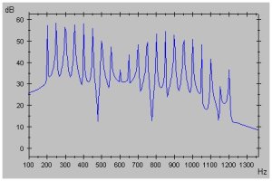
So if we keep computing samples by the last expression, while the value of t (the time, measured in seconds) is increased by 1/Samplerate each sample, we obtain a waveform with a harmonic spectrum. Telling by the equation, the properties of the generated spectrum are as follows: There are N+1 partials, the fundamental is fc (which shall be called center frequency), the distance between two subsequent partials is fm (which shall be called modulation frequency), and the partials' magnitudes fall off by factor a, which shall be called the amplitude ratio. On a decibel scale, the partials fall off linearly.
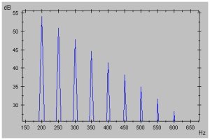 |
| Spectrum of a DSF-generated waveform with N = 8, fc = 200, fm = 50, and a = 0.7. |
Moorer also provides a formula for two-sided spectra, ie. for partials falling off on both sides of the center frequency.
Complex DSF Synthesis
Now, we can add some more variety to the generated spectra
by substituting the amplitude ratio with a complex number, say
a ® r
(cosg + i sing). Then we
gather:|
N ∑ ak sin(q + kb) k = 0 |
= |
N ∑ (r (cosg + i sing))k sin(2p(fc + k fm) t) k = 0 |
| = | N ∑ rk cos(kg) sin(2p(fc + k fm) t) k = 0 |
+ |
N i ∑ rk sin(kg) sin(2p(fc + k fm) t) k = 0 |
|
||
| Spectra of the real signal (left) and imaginary signal (right) for N = 20, fc = 200, fm = 50, a = 0.95, and g = 0.285 p. |
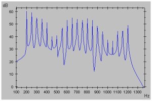
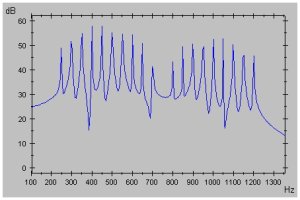
The idea of using complex numbers as amplitude ratios was already mentioned by Stilson and Smith. Yet, their assumption that this would be equivalent to summing a real DSF signal with a shifted version of itself, possibly with a sign flip, is wrong. With complex DSF, the magnitudes of the partials are independent of the center frequency and modulation frequency. So the sound preserves its character even if the pitch is changed. This could not be achieved by superposing a real DSF signal with a shifted dublicate of itself, since that would create a comb pattern anchored at 0 Hz and not at the center frequency.
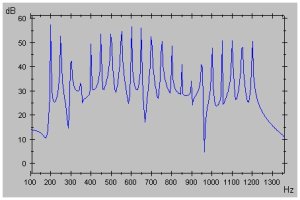
In addition, complex DSF makes it possible to shift the comb patterns by simply multiplying the complex signal with another complex number. If we multiply the complex samples with (cosj + i sinj), for some j, the resulting signal is:
|
N ∑ rk cos(j + kg) sin(2p(fc + k fm) t) k = 0 |
+ |
N i ∑ rk sin(j + kg) sin(2p(fc + k fm) t) k = 0 |
|
||
| Real and imaginary spectrum of the signal above after the complex samples have been multiplied with (cosj+ i sinj), where j = 0.25 p. By the multiplication, the combs have been shifted. |
How to use Miffi
Basically, Miffi generates a complex DSF signal and morphs between two DSF parameter sets to produce a waveform that changes over time. The resulting real and imaginary signals are combined into a stereo signal.Morphing
The two DSF parameter sets that limit the morphing range can be defined in the Oscillator section.Example: Take a look at the example picture of Miffi. The range of the DSF parameter Ampl. Ratio goes from 0.665 to 0.481, the range of Comb Angle goes from -0.010 to 1.43, and the range of Comb Phase goes from 0.440 to -0.030. All other DSF parameters have been fixed to certain values by setting the same value in the upper and lower row. Now, if Miffi morphs a voice, it does so for all DSF parameters simultaneuously. If, for instance, morphing starts at the parameter set defined in the lower row and ends at the parameter set in the upper row, the oscillator will be fed at the beginning with an Ampl. Ratio, Comb Angle and Comb Phase of 0.665, -0.010, and 0.440, respectively. Then, while morphing, the oscillator's Ampl. Ratio, Comb Angle and Comb Phase inputs will gradually and simultaneously change until they reached the values 0.481, 1.74, and -0.030, respectively.
The starting and end point of the morphing can be altered in the Range Control section. The RangeL slider determines the start parameter set and the RangeR slider determines the end parameter set of the morping. Alternatively, the joystick knob in the square can be used to alter both start and end parameter sets at the same time.
Example: If RangeL is at the topmost position and RangeR is at the bottommost position, the oscillator will be initially fed with the DSF parameter values defined in the top row of the Oscillator section. As an aid, the start parameter set will be indicated by the left red triangle in the Morph Range field, which, in this example, will point to the top row. When a note is played, the DSF input of the oscillator will be gradually changed into the values defined in the bottom row of the Oscillator section, as determined by the RangeR slider. The end point will be indicated by the right red triangle, which will point to the bottom row. If, for instance, the sliders' positions are changed such that RangeL is in the middle position and RangeR is at the topmost position, then morphing will start at a parameter mix within the ranges defined by the upper and lower row, and morphing will end at the set of values defined in the upper row.
The range sliders and the joystick knob provide a simple but effective means to change the sound of the synth while playing.
Now, Miffi doesn't just linearly morph from one parameter set to another. The way in which Miffi morphs between the start and end parameter sets is defined by the Morph Mode selector.
Example: If the selector is set to ADSR2, and a note starts playing, then morphing will start at the parameter set determined by RangeL, then it will proceeed to the parameter set specified by RangeR, and when the note is released, morphing will go back to the set specified by RangeL again. The speed at which all that happens is controlled by the ADSR 2 envelope.
Oscillator Settings
The overall ranges of the morphable DSF parameters can be defined in the Oscillator section:- Ampl.Ratio: This is the amplitude ratio, ie. the variable r in the complex DSF formula. It defines how fast the partials fall off.
- M :
C Ratio: These
knobs determine the modulation frequency fm.While
the center frequency fc is specified by
the
currently played note and the Pitch
settings, fm is
computed as fm = fc
* m/c +
offset, where the range of m is defined by the knob pair on
the left below the "M : C Ratio" label and the range of c is
defined by the knob pair on the right below that label. The
range of "offset" is defined by the knob pair below the label
"M-Offset".
m can also be negative.Then the partials right of the center frequency will be flipped to the left. By that, some partials may be inverted, ie. they have negative frequencies. Those will be mirrored back into the positve frequency range. - M-Offset: See the description of M : C Ratio above. Choosing non-zero values for M-Offset usually detunes the sound but can lead to interesting effects.
- Pitch: Alters the pitch, measured in octaves. That is,. a value of 1 means that the note is played one octave higher.
- Comb
Angle: This
reflects the g
variable in
the DSF formula, measured in multiples of p.
This parameter influences the distance
between peaks of the comb patterns. Some examples on how the
combs are altered by the Comb Angle value:
- At 0, there is no comb pattern at all.
- Gradually increasing the value till 0.5 will create peaks, growing denser and denser.
- At 0.5, the peaks are as dense as they get. In the real spectrum, the peaks are identical with the 1st, 3rd, 5th,... partials, and the 2nd, 4th etc. partials are missing (btw, the 3rd, 7th etc. partials are inverted) . In the imaginary spectrum, it's the other way around.
- Increasing the value till 1 will increase the distance between peaks again. At 1, the comb has vanished (yet, it's technically not the same as 0 since the signs of the partials are now alternating; every second partial is inverted).
- Going from 0 to -1 is analog, the partials are just inverted.
- Comb
Phase: This
reflects the variable j,
ie. the
comb phase offset, measured in multiples of p.
If the comb angle value is positive,
gradually increasing the comb phase value will shift the comb
pattern towards 0 Hz (ie. usually to the left, unless the
partials are inverted), and decreasing the value will move
the comb in the other direction. Some special comb phase
values:
- At 0, there's no phase shift at all.
- At 1, the peaks overlap again, yet every second partial is inverted.
- At 2, it's the same as at 0.
- Going from 0 to negative values will move the comb in the other direction.
- If the comb angle value is 0, then there will be no comb pattern. If also the comb phase value is 0, only the real signal is audible. In L+R stereo mode, you would hear sound only from the left speaker box. Changing the comb phase value now to a non-zero value would shift the partials from the real signal to the imaginary signal, ie. in L+R mode the sound would wander to the right speaker box.
Sidebands: This control reflects the variable N in the DSF formula, ie. the number of partials on either side of the center frequency. Notice that the oscillator, independent of this setting, will automatically cut off partials that are higher than half the samplerate to avoid aliasing (eg. when sampling at 44 kHz, partials above 22 kHz will not be generated by the oscillator; when sampling at 96 kHz, the limit is 48 kHz etc).
Symmetry: If this is set to 1-sided, then there will be only partials to the right of the center frequency. If it is set to 2-sided, then there will be also partials to the left of the center frequency. The partials to the left may reach into the negative frequency range; then they will be mirrored back into the positive range, where they may overlap with other partials and create beating effects.
Range Control
RangeL, RangeR: As already mentioned in the Morphing section, RangeL and RangeR determine the mix of DSF parameter values at which the morphing starts and ends, respectively. Alternatively, the joystick knob can be used to alter both range limits simultaneously.Effect: This control only matters when you change the range limits with the Range sliders or the joystick knob while playing. When Effect is set to "Continuous", moving the Range sliders or the joystick knob while playing will affect the sound of all voices simultaneously. But when it's set to "Per Note", then each voice remembers the current Range setting at the moment it starts playing a note, and it keeps that setting until it's finished.
Morph Mode
Morph Mode: With this control you can select how the morphing proceeds between the start and end parameter sets.- RangeL: At this setting, no morphing happens but the oscillator will be statically fed with the mix of parameter values determined by the RangeL slider.
- RangeR: Like RangeL, but for the RangeR slider.
- ADSR1: The morphing will be controlled by the
envelope ADSR
1 (which also controls the volume while a note is playing).
- Morphing first goes from the start parameter set to the end parameter set at the speed specified by Attack.
- Then it goes back to a parameter set corresponding to Sustain. If the Sustain slider is at the topmost position, then this parameter set is the end parameter set determined by RangeR; if it's at the bottommost position, the Sustain parameter set is the end parameter set determined by RangeL; and if Sustain is somewhere in the middle, then the parameter set is a mix between the start and end parameter set.
- The speed at which the Sustain level is reached is specified by the Decay slider. Once Sustain level is reached, morphing stays there until the note is released.
- When the note is released, morphing will go back to the RangeL parameter set at a speed specifed by Release.
- ADSR2: Similar to ADSR1, but now it's the ADSR 2 envelope controlling the morphing.
- LFO: Morphing will oscillate between the start
parameter
set and end parameter set. The oscillation is controlled by the
LFO (Low Frequency Oscillator) and ADSR 2:
- ADSR 2 controls the magnitude of the oscillation while a note is played.
- Speed: Determines the frequency of the oscillation.
- Sync: If this is activated, the oscillation will be synchronized to the song tempo.
- Amt: Specifies the maximum magnitude of the oscillation.
- Waveform: The waveform of the oscillation (Only Sine or Triangle. Waveforms with discontinuities were omitted since those caused unpleasant popping sounds).
Stereo Mode
The way the real and imaginary signals are output as stero pairs can be influenced by the following controls.Stereo: With this control, you select the stereo coding.
- L+R: The real signal is mapped to the left stereo channel and the imaginary signal is mapped to the right stereo channel.
- M+S: The real signal is output as the middle component and the imaginary signal is output as the side component (that is, the left channel output is the sum of the real signal and the imaginary signal, and the right channel output is the difference between the real signal and the imaginary signal).
- S+M: The real signal is output as the side component and the imaginary signal is output as the middle component.
- alt: In modes marked with the suffix "alt", the left and right output channels alternate, ie. they are swapped every time a voice starts playing a new note.
MIDI
By the help of the MIDI learn function, you can easily assign parameters to MIDI-CCs. This is how it works (it may not work though on hosts that catch MIDI signals to implement their own learn function):- Hit the Learn button. The red LED next to it is lit to indicate that you're now in MIDI learn mode.
- Move the knob/slider/button you wish to control.
- Move the MIDI control which you want to assign to it. The red LED is unlit again to indicate that you left MIDI learn mode.
Miffi instances that share the same Map-ID also share the same MIDI-CC mapping. So if you want use more than one MIDI-CC mapping, you have to alter the Map-IDs by the Map-ID selector accordingly. The mappings are stored as plain text files in the Miffi plugin folder, in folders named mfmidi00, mfmidi01, and so forth.
Miscellaneous
ADSR 1: Controls the volume of a voice while it's playing a note. The volume starts at zero and goes to maximum at the speed specified with Attack. Then it goes back to Sustain level, at the speed defined with Decay. Finally, when the note is released, volume goes back to zero at the speed specified by Release.Voices: The maximum amount of voices that can be active at the same time. It can be freely set between 1 and 16. This is supposedly an unusual feature for a Synthedit synth since Synthedit doesn't provide means to change polyphony on the fly, but Miffi works around this.
Slide: This is the portamento speed, ie. the speed at which notes slide. To make notes slide, a key must not be released before the next key is pressed. If the Slide knob is turned to the leftmost position, sliding is off. ADSR 1 behaves special if sliding is turned on and Voices is set to 1; in this case, the attack volume doesn't start at zero but it starts from the current level..
Volume: Limits the overall volume.
HQ: High Quality. Turning this on makes the signal quality better at cost of processing time. However, don't expect to hear any difference: When HQ is disabled, the noise added is at worst 116 dB lower than the audible signal, which isn't audible in a 16-bit recording. Anyway, I kept this in, so when you're rendering, you may want to enable it.
Bend Range: This is the pitch bend range measured in half tones. If you're using a pitch bend wheel, you may have to alter this parameter to get the desired effect.
Finally, a note on the controls: The DSF parameter controls have text entry fields which you can use to enter exact values. The sliders can be moved with more precision when you press CTRL while moving them. And to turn the knobs with more precision, click on them, then move the mouse pointer away while keeping the mouse button pressed; the farther away the mouse pointer is, the more precise will be the turning of the knob.
Installation
Put the file Miffi.dll into your VST Plugins folder. Literature
James
A. Moorer, "The
Synthesis of Complex Audio Spectra by Means of Discrete Summation
Formulas", http://www.jamminpower.com/main/articles.jsp,
1976.Tim Stilson, Julius Smith, "Alias-Free Digital Synthesis of Classic Analog Waveforms", http://ccrma.stanford.edu/~stilti/papers, 1996.
Version History
Miffi v1.1:Fixed crash when the modulation frequency was zero and the center frequency exceeded 22kHz.
Improved CPU check to avoid crashes on older machines.
New background image.
Miffi v1.0:
Initial release.
Thanks to
Vera Kinter (designer of the knob, button, and slider skins, http://www.artvera-music.com)David Haupt (creator of the MIDI ControlMeister module,http://www.dehaupt.com/SynthEdit/index.html)
Jeff McClintock (creator of Synthedit, http://www.synthedit.com)
Contact
You can contact me by E-Mail at: moppelsynths@verklagekasper.de (Burkhard Reike).DISCLAIMER:
This software is provided as is, there is no warranty and nobody is responsible for any kind of damage. Use it at your own risk.VST is a trademark of Steinberg Soft- und Hardware GmbH, Germany.
 |
 |
Privacy Policy